Diagrams: Here are our system and energy dataflow diagrams
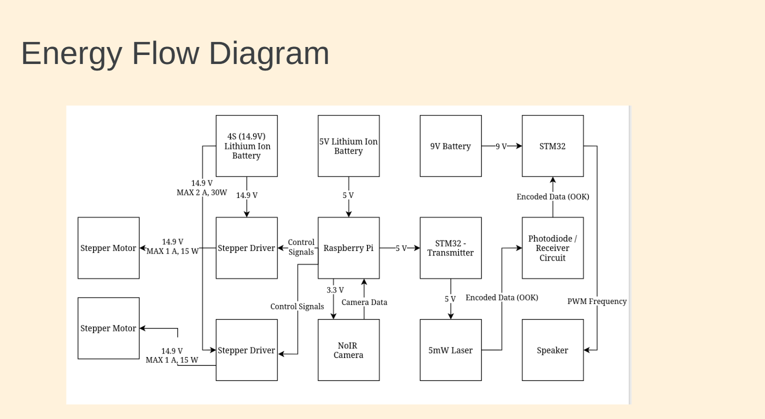
Energy Flow Diagram
There are two different systems with different power requirements, and as such, we have multiple different power sources. A 14.9V Lithium Ion battery that provides power to the motor drivers and the motors. The motor drivers get their control signal from the central RasPi, powered from a separate 5V Lithium Ion battery. That RasPi also provides power to the NoIR camera, which feeds IR camera data back for processing tracking information. Finally, the RasPi provides input power to an STM32, which is responsible for switching the FET controlling the laser. That subsystem is completely electrically isolated from the next. The Receiver STM32 is powered from a 9V battery and is responsible for reading the changing voltages from the photodiode sensor, processing data, and outputting PWM signal to a speaker.
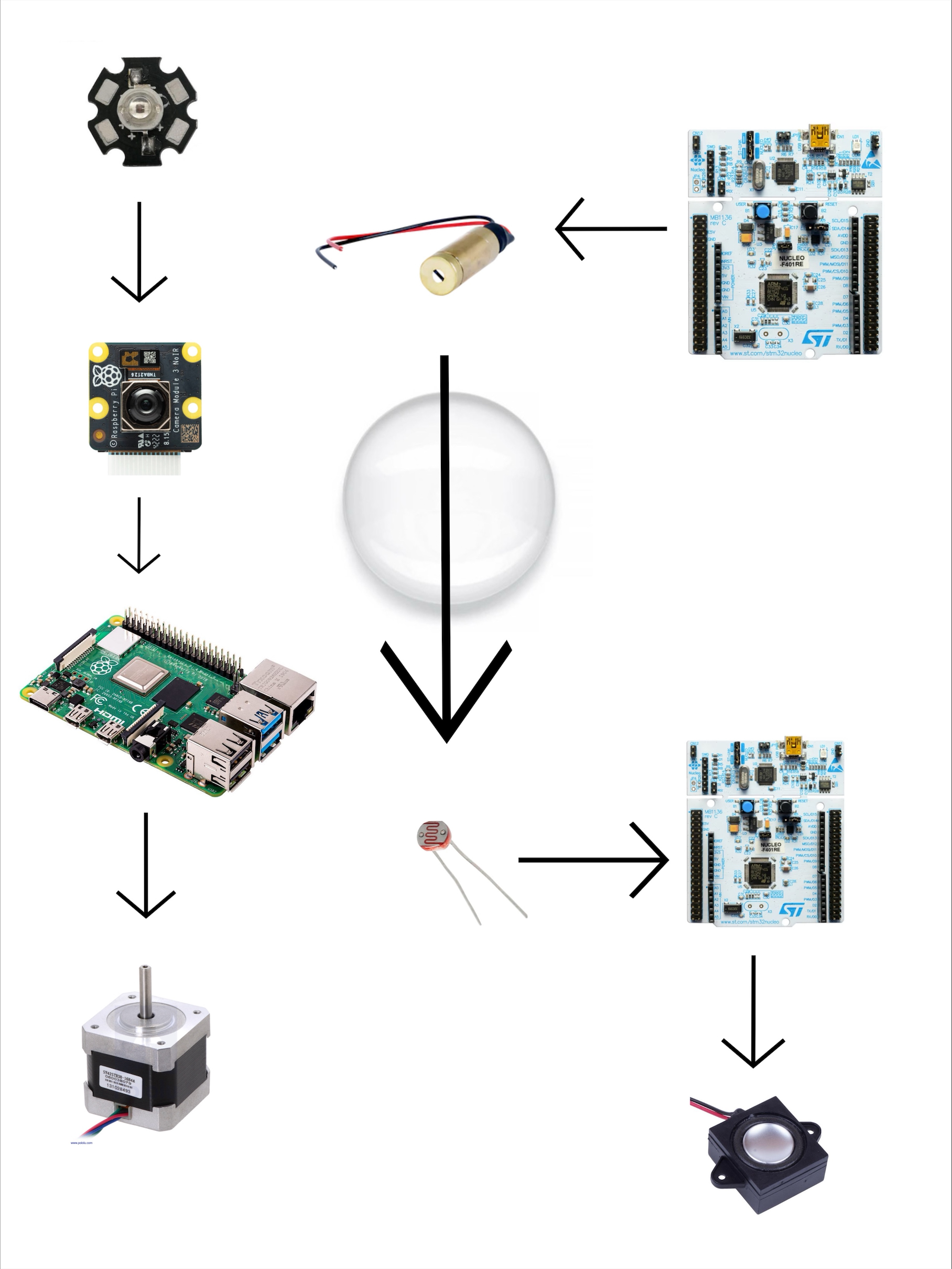
High Level System Diagram
This diagram shows two of our subsystems, the camera tracking system and laser data transmission system. You can see in the diagram the camera tracking system operates by the Rasperbrry Pi taking signals from the IR LED, and using that data to figure out what data to send to the motors. The transmission system can be seen starting with the laser taking commands from the STM32, that then sends its data through a lens, to a photodiode that takes the light input and sends the recieved data to the recieveing end STM32 that decrypts the data, and sends the gained information to a speaker.