Electrical: Key Systems & Schematics
Transmitter
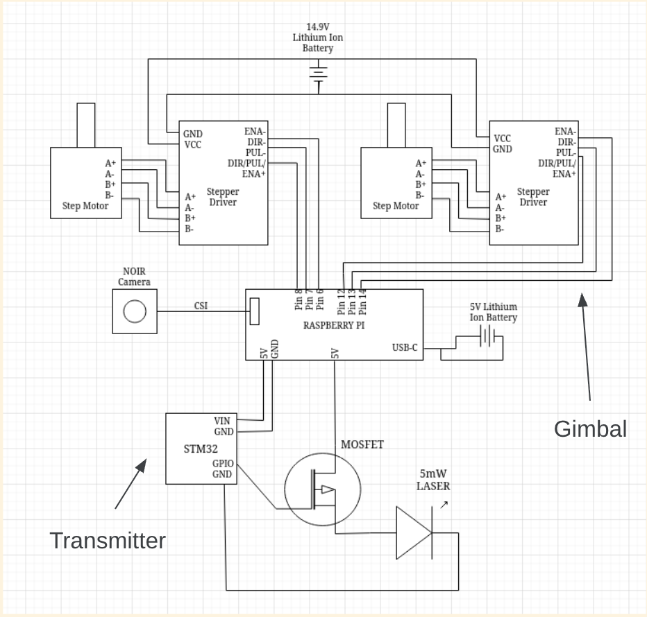
Transmiter Schematic
This was the first circuit we put together. We're using a MOSFET to pulse the laser acording to an output from the STM32. Also visible is the connection through the RasberyPi, which acts as a central hub for our entire transmiter. All of the other transmitter components are invovled in tracking, the camera passing photo data and the motors creating a pan-tilt gimbal. This circuit worked the first time we tested it and was not updated since.

Implemented Transmiter
The laser pulse circuit is relativly straight forward. There were no major design choices other than the use of a MOSFET as a switch, which was arbitrary and worked in testing. The specific laser that we used was chosen for it's low power, meaning it wouldn't be difficult to power from the RasberyPi, and there are fewer saftey concerns.
Receiver
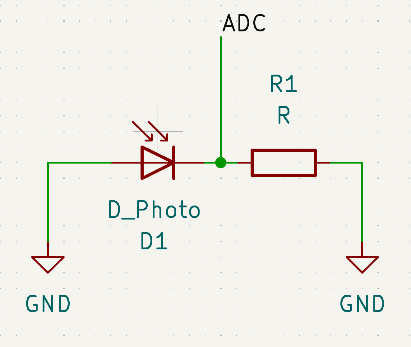
Receiver Schematic:
This was our initial receiver design, we use a photodiode to act as a current source whenever the laser hits it, which runs current through a resistor to ground, and the voltage across the resistor is read by the ADC of our STM32.

First Implemented Prototype:
Here’s our implementation on a perf board. This was used for preliminary testing of the pulse reading. Even though there's no protections to counteract the CR filter created by the photodiode capacitance and the sensing resistor, the output waveforms were clear and the voltages were sufficiently different to be easily read. When testing movment of the laser, we found that the voltage output became unreliable, so we choise to use a focusing lens infront of the photodiode to try and keep the beam centered.
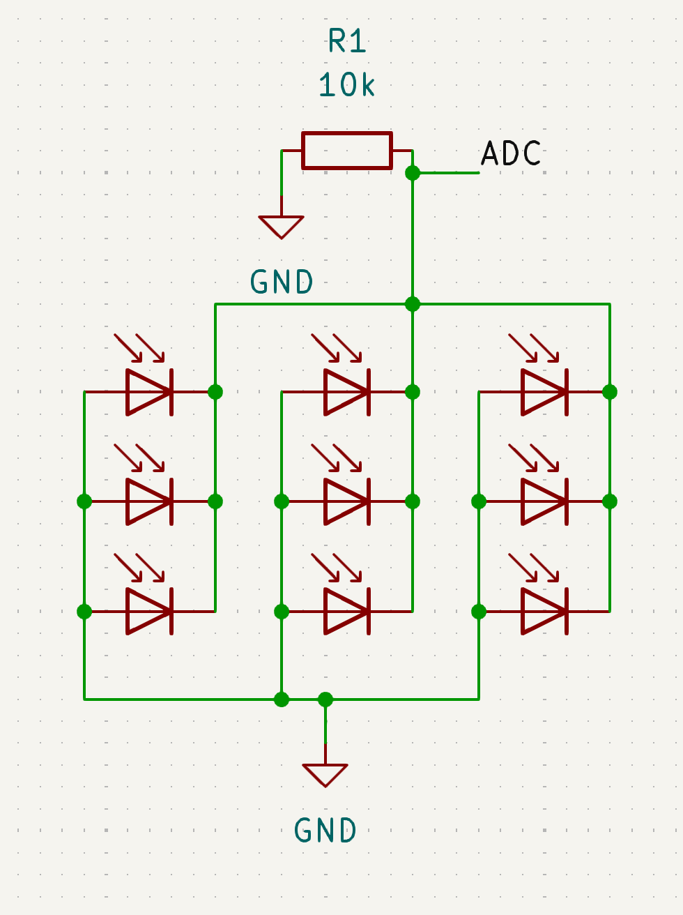
Photodiode Array Schematic:
We found that, when the laser was on the edge of the lens, it could only partially hit the single photodiode. The small size of the photodiode could lead the beam only hitting part of it, and thus we would read voltage somewhere between our data high and data low values. To avoid this, we chose to set up a photodiode array as seen in the schematic. This increases the effective capacitance, but we still found it to be negligible.
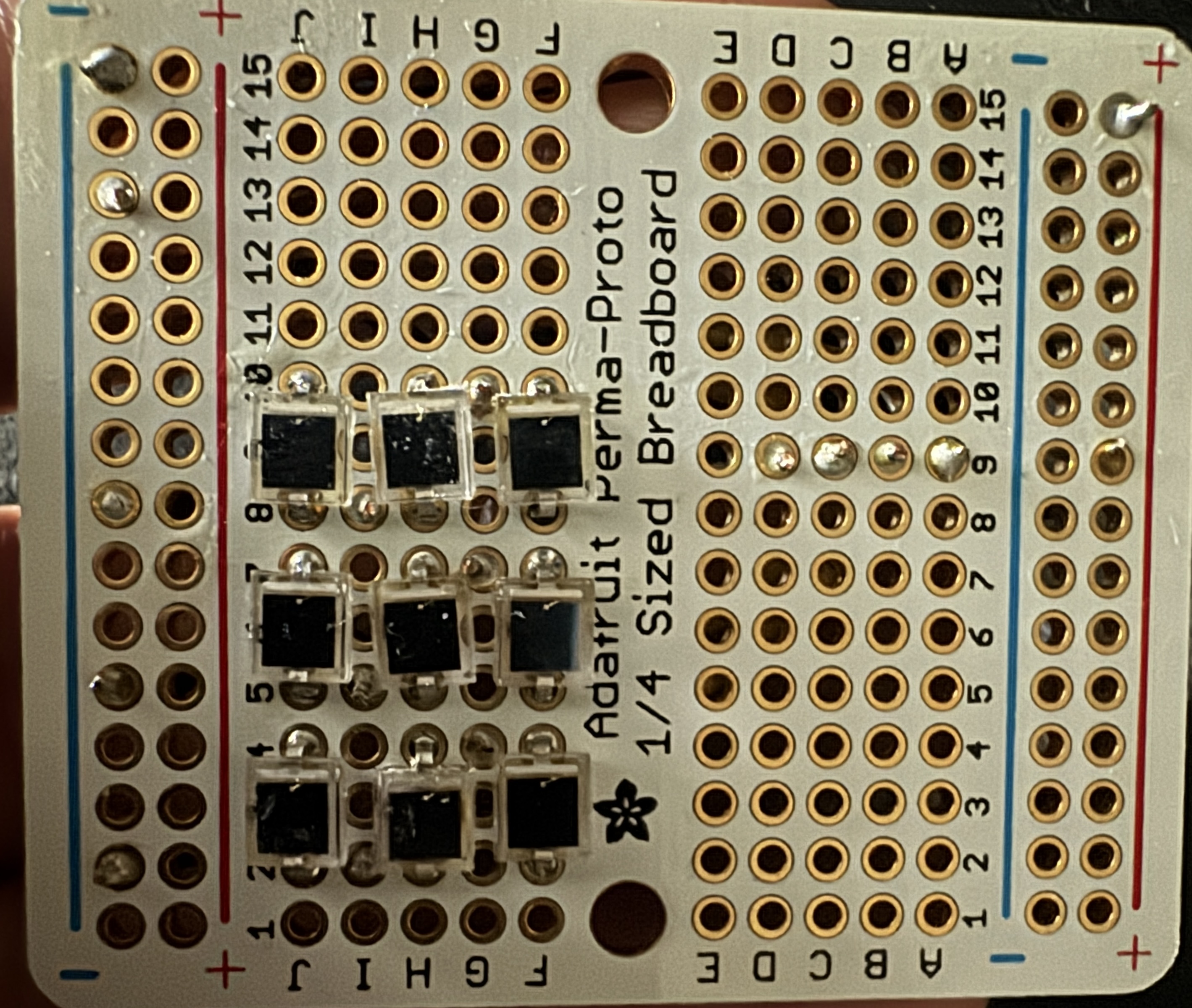
Implemented Phodiode Array:
Here’s the photodiode array assembled on a protoboard. The physical construction of the array was slightly challenging as we needed all of the photodiodes to be close enough that they would effectively act as one larger photodiode, but they each needed to have separate connections to a shared ground. Aside from the soldering trouble, this circuit worked quite well and we were able to get very distinct high vs low voltage readings, even when the laser was off to the side of the receiver lens.
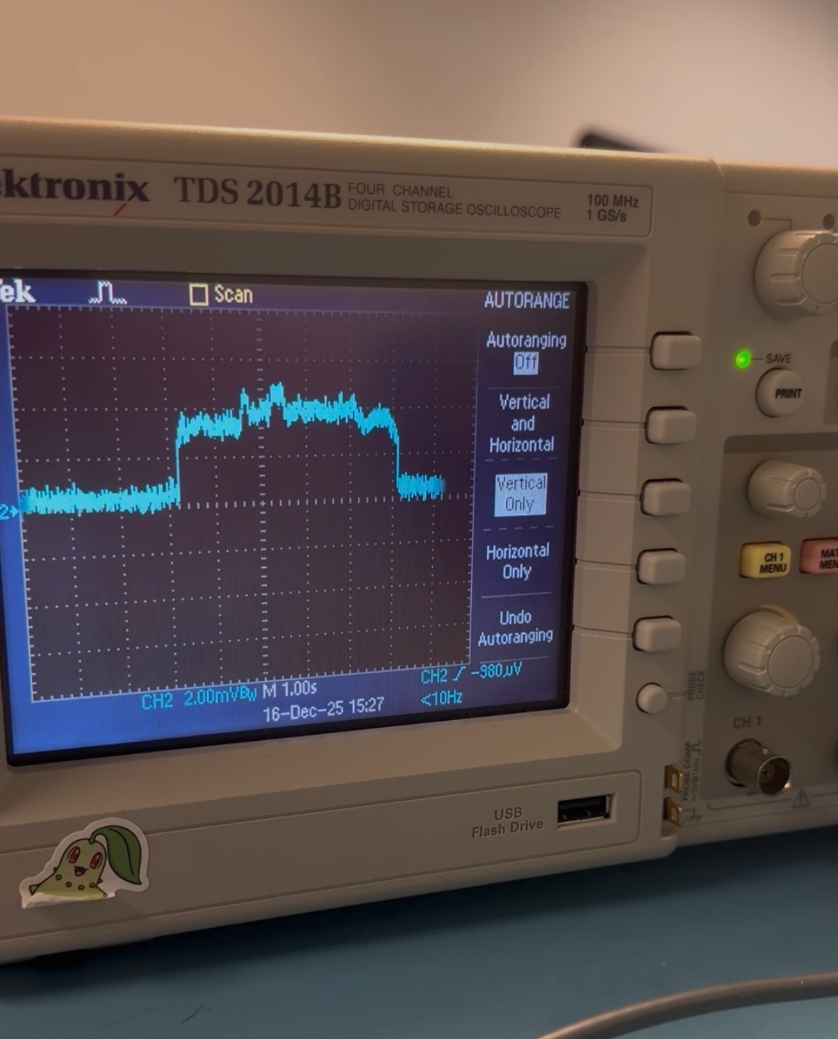
Photodiode Array Waveform:
We tested the photodiode array output waveform on a scope and saw that the output was, while a bit noisy, still had easily distinguishable high and low values. That lead us to stick with this design for the final receiver circuit.
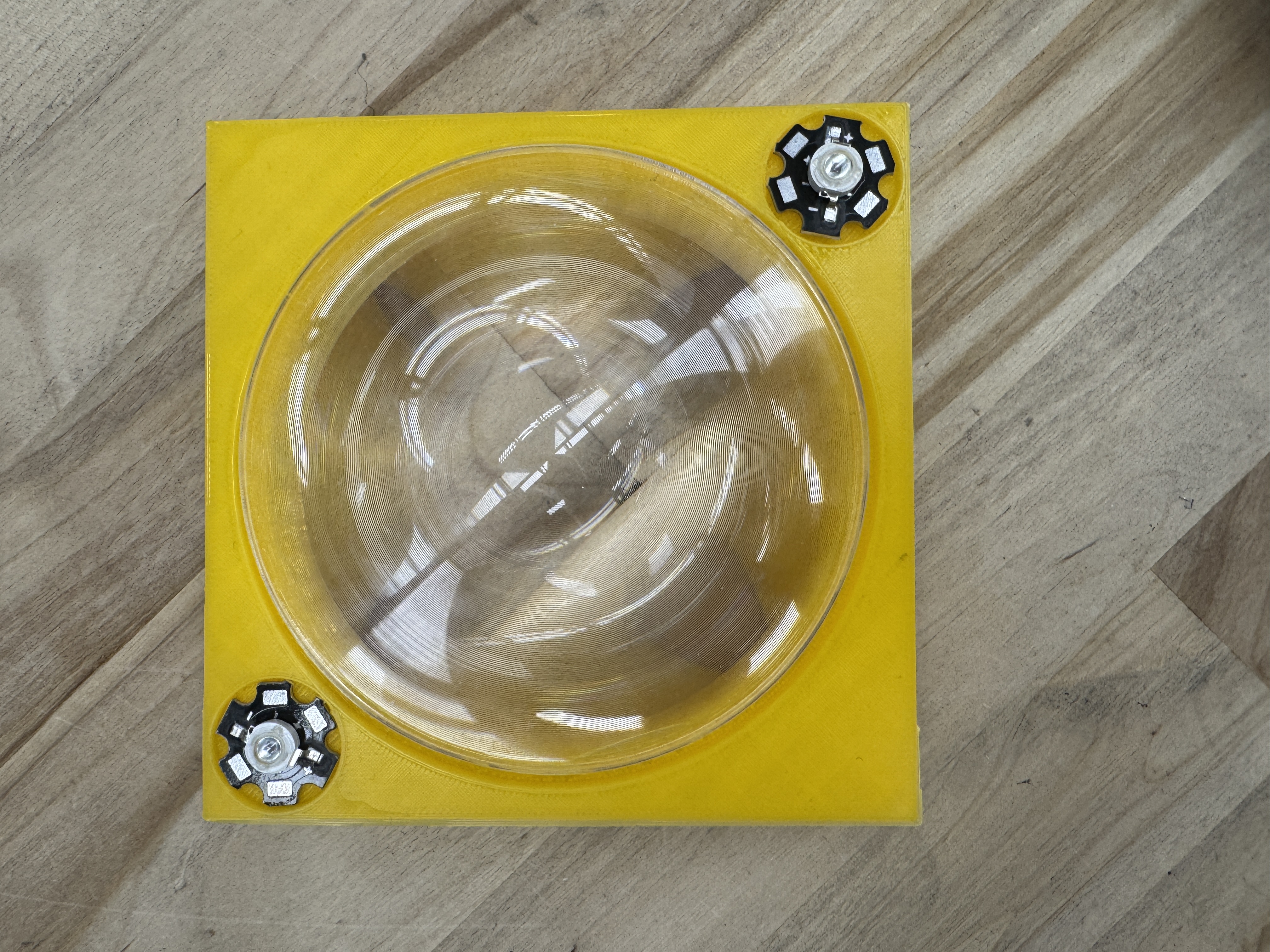
Focusing Lens
This is the first design that implemented the focusing lense. We opted to use a Fresnel lens as it was easy to get and did a good job of focusing the beam.