2-LED Midpoint Tracker:
- Drives a two-axis laser mount to lock onto the midpoint between two LEDs. Uses PiCamera2 for imaging, OpenCV for detection, and GPIO-driven steppers for pan/tilt. Operators can switch between auto tracking and manual jog, and re-base the lock target with an offset.
Hardware and Motion:
BCM pin map feeds step/dir for pan and tilt with optional inversions to match mechanics. Step timing separates auto cadence from manual jog. A balanced stepping routine keeps both axes coordinated.
Imaging and Detection:
Runs 640x480 with locked exposure and gain to stabilize LED brightness. Thresholding plus contour filtering selects the two brightest blobs; their centers define the midpoint target.
Modes and Controls:
A auto track, M manual, S set offset to current midpoint, R reset offset to center, arrow keys for jog, Q quit. Dead-zone prevents jitter; send cadence throttled by SEND_PERIOD.
Visualization and Safety:
Overlay shows lock target, LED contours, midpoint, and error vector, with status text for mode. Cleanup stops camera and clears GPIO; mock GPIO warns when off-Pi.
Software/Firmware Narrative:
Document the end-to-end software stack, firmware choices, and dependencies (e.g., OpenCV, PiCamera2, Raspberry Pi OS). Summarize major trade-offs, integration steps, and link to the full source repo.
Software dependencies (runtime):
-
The project began with a naïve brightest-pixel tracking approach, which immediately exposed a critical limitation: the system repeatedly locked onto ambient light sources such as ceiling fixtures and reflections rather than the intended LEDs. This led us to abandon pure intensity-based detection in favor of object-level reasoning, introducing blob-based detection with spatial filtering to reject large illuminated regions and noise. While this significantly improved robustness, we encountered instability when LED blooming caused blob centroids to drift as distance and exposure changed. To address this, we redesigned the target hardware to use two LEDs instead of one and transitioned to tracking their midpoint, which provided geometric redundancy and a far more stable reference. As vision performance improved, control-related issues became apparent: motor motion was often inverted relative to image-plane error due to wiring and mounting inconsistencies, which we resolved by abstracting axis inversion entirely into software. We also corrected an early control-law mistake in which the system attempted to move toward offsets rather than eliminate them, reformulating the controller as a true negative-feedback loop with a dead zone to prevent oscillation near the target. A deeper physical limitation emerged from the non-coaxial mounting of the camera and laser, causing parallax offsets that made visual centering insufficient for accurate laser pointing. This problem worsened with changes in depth, rendering any fixed calibration invalid. Instead of attempting unreliable geometric modeling, we adopted a human-in-the-loop calibration strategy in which the system records a visually aligned lock point at each new depth and maintains alignment thereafter. Finally, we addressed system-level integration challenges, including timing conflicts between camera frame rate and motor actuation, by throttling control updates and introducing explicit operational modes that allow manual override and recovery without restarting the system. Through approximately fifteen iterations, these combined solutions transformed the system from a fragile proof of concept into a stable, adaptable, and physically grounded tracking platform.
Code:
# decoder.py — snippet
import time
import cv2
import numpy as np
from picamera2 import Picamera2

try:
    import RPi.GPIO as GPIO
except (ImportError, RuntimeError):
    GPIO = type("MockGPIO", (), {"__getattr__": lambda self, name: print(f"[MOCK] Ignored GPIO call: {name}")})()

STEP_PIN_X = 4
DIR_PIN_X = 3
STEP_PIN_Y = 11
DIR_PIN_Y = 9

INVERT_Y_MOTOR_FOR_PAN = True
INVERT_X_MOTOR_FOR_TILT = False

STEP_DELAY = 0.0001
MOTOR_STEP_SIZE = 10
MANUAL_STEP_SIZE = 5

picam2 = Picamera2()
picam2.configure(picam2.create_preview_configuration(main={"size": (640, 480)}))
picam2.start()
time.sleep(0.5)

try:
    picam2.set_controls({"AeEnable": False, "AwbEnable": False, "ExposureTime": 4000, "AnalogueGain": 1.5})
except Exception as e:
    print(f"Could not set camera controls: {e}")

W, H = 640, 480
CENTER_X, CENTER_Y = W // 2, H // 2

SEND_PERIOD = 0.1
DEAD_ZONE_PIXELS = 10
MIN_BRIGHTNESS_THRESHOLD = 150
MIN_CONTOUR_AREA = 25

def setup_gpio():
    GPIO.setmode(GPIO.BCM)
    GPIO.setup([STEP_PIN_X, DIR_PIN_X, STEP_PIN_Y, DIR_PIN_Y], GPIO.OUT)

def move_xy(sx, sy):
    GPIO.output(DIR_PIN_X, GPIO.HIGH if sx > 0 else GPIO.LOW)
    GPIO.output(DIR_PIN_Y, GPIO.HIGH if sy > 0 else GPIO.LOW)
    ax, ay = abs(sx), abs(sy)
    max_steps = max(ax, ay)
    if max_steps == 0:
        return
    err_x, err_y = max_steps // 2, max_steps // 2
    for _ in range(max_steps):
        err_x -= ax
        if err_x < 0:
            err_x += max_steps
            GPIO.output(STEP_PIN_X, GPIO.HIGH)
        err_y -= ay
        if err_y < 0:
            err_y += max_steps
            GPIO.output(STEP_PIN_Y, GPIO.HIGH)
        time.sleep(0.000001)
        GPIO.output(STEP_PIN_X, GPIO.LOW)
        GPIO.output(STEP_PIN_Y, GPIO.LOW)
        time.sleep(STEP_DELAY)

print("Starting Tracker.")
print(" CONTROLS:")
print("  [A] - Auto Mode (Follow LEDs)")
print("  [M] - Manual Mode (Stop tracking logic)")
print("  [S] - SET OFFSET (Records current LED pos as new target)")
print("  [R] - RESET OFFSET (Back to screen center)")
print("  [Arr] - Move motors manually")
print("  [Q] - Quit")

setup_gpio()
last_send_t = 0.0
is_auto_mode = True
target_lock_x = CENTER_X
target_lock_y = CENTER_Y

try:
    while True:
        frame_bgr = picam2.capture_array()
        gray = cv2.cvtColor(frame_bgr, cv2.COLOR_BGR2GRAY)

        _, threshold_img = cv2.threshold(gray, MIN_BRIGHTNESS_THRESHOLD, 255, cv2.THRESH_BINARY)
        contours, _ = cv2.findContours(threshold_img, cv2.RETR_EXTERNAL, cv2.CHAIN_APPROX_SIMPLE)

        valid_contours = []
        for cnt in contours:
            area = cv2.contourArea(cnt)
            if area > MIN_CONTOUR_AREA:
                M = cv2.moments(cnt)
                if M["m00"] != 0:
                    cX = int(M["m10"] / M["m00"])
                    cY = int(M["m01"] / M["m00"])
                    valid_contours.append({"contour": cnt, "area": area, "center": (cX, cY)})

        valid_contours.sort(key=lambda x: x["area"], reverse=True)

        current_led_mid_x, current_led_mid_y = CENTER_X, CENTER_Y
        led1, led2 = None, None
        target_found = False

        if len(valid_contours) >= 2:
            led1 = valid_contours[0]
            led2 = valid_contours[1]
            current_led_mid_x = (led1["center"][0] + led2["center"][0]) // 2
            current_led_mid_y = (led1["center"][1] + led2["center"][1]) // 2
            target_found = True

        key = cv2.waitKey(1) & 0xFF

        if key == ord("q"):
            break
        elif key == ord("a"):
            is_auto_mode = True
        elif key == ord("m"):
            is_auto_mode = False
        elif key == ord("r"):
            target_lock_x, target_lock_y = CENTER_X, CENTER_Y
        elif key == ord("s") and target_found:
            target_lock_x = current_led_mid_x
            target_lock_y = current_led_mid_y

        step_x, step_y = 0, 0
        status_text = ""
        status_color = (0, 255, 0)

        if is_auto_mode:
            if target_found:
                offx = current_led_mid_x - target_lock_x
                offy = current_led_mid_y - target_lock_y
                if abs(offx) > DEAD_ZONE_PIXELS:
                    step_y = -MOTOR_STEP_SIZE if offx > 0 else MOTOR_STEP_SIZE
                if abs(offy) > DEAD_ZONE_PIXELS:
                    step_x = -MOTOR_STEP_SIZE if offy > 0 else MOTOR_STEP_SIZE
                status_text = "AUTO: TRACKING"
            else:
                status_text = "AUTO: SEARCHING"
                status_color = (0, 165, 255)
        else:
            status_text = "MANUAL MODE"
            status_color = (0, 0, 255)
            if key == 82:
                step_x = MANUAL_STEP_SIZE
            elif key == 84:
                step_x = -MANUAL_STEP_SIZE
            elif key == 81:
                step_y = MANUAL_STEP_SIZE
            elif key == 83:
                step_y = -MANUAL_STEP_SIZE

        if INVERT_X_MOTOR_FOR_TILT:
            step_x = -step_x
        if INVERT_Y_MOTOR_FOR_PAN:
            step_y = -step_y

        now = time.time()
        if not is_auto_mode and (step_x != 0 or step_y != 0):
            move_xy(step_x, step_y)
        elif is_auto_mode and (now - last_send_t) >= SEND_PERIOD:
            if step_x != 0 or step_y != 0:
                move_xy(step_x, step_y)
            last_send_t = now

        cv2.drawMarker(frame_bgr, (target_lock_x, target_lock_y), (255, 0, 255), cv2.MARKER_CROSS, 30, 2)

        if target_found and led1 and led2:
            cv2.drawContours(frame_bgr, [led1["contour"], led2["contour"]], -1, (255, 0, 0), 2)
            cv2.line(frame_bgr, led1["center"], led2["center"], (0, 255, 255), 2)
            cv2.circle(frame_bgr, (current_led_mid_x, current_led_mid_y), 10, (0, 255, 0), -1)
            if is_auto_mode:
                cv2.line(frame_bgr, (current_led_mid_x, current_led_mid_y), (target_lock_x, target_lock_y), (255, 255, 255), 1)

        cv2.putText(frame_bgr, status_text, (10, 30), cv2.FONT_HERSHEY_SIMPLEX, 0.7, status_color, 2)
        cv2.putText(frame_bgr, "[S] Set Offset  [R] Reset", (10, H - 40), cv2.FONT_HERSHEY_SIMPLEX, 0.6, (200, 200, 200), 1)
        cv2.putText(frame_bgr, "[A] Auto  [M] Manual", (10, H - 20), cv2.FONT_HERSHEY_SIMPLEX, 0.6, (200, 200, 200), 1)

        cv2.imshow("2-LED Tracker", frame_bgr)

finally:
    cv2.destroyAllWindows()
    picam2.stop()
    GPIO.cleanup()
Transmission and Reception:
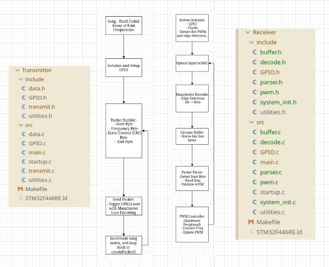
System Overview
The STM32-based laser communication system consists of a transmitter and a receiver, designed to explore low-level embedded control and optical signal processing. The transmitter modulates a visible laser using Manchester line encoding, while the receiver measures the incoming light with BPW34 photodiodes and converts it to a digital signal for decoding. The system emphasizes bare-metal programming to maximize learning, giving full access to timers, GPIOs, and ADCs without abstraction layers.
Transmitter Architecture
The transmitter firmware generates a precise digital waveform to drive the laser at a target data rate of 10 kbits/sec. Manchester encoding ensures embedded clock information, simplifying synchronization at the receiver. Output timing is controlled by STM32 timers to maintain bit periods with microsecond precision. The architecture includes a simple state machine to handle start-of-packet detection, bit generation, and optional pauses for signal integrity, while minimizing resource usage on the microcontroller.
Receiver Architecture
The optical front end uses a BPW34 photodiode with a single series resistor, eliminating the need for a complex transimpedance amplifier. The voltage across the resistor is sampled using the STM32 ADC at a high frequency. The decoding firmware implements a real-time Manchester decoding algorithm using a timer-driven sampling loop. Each sample is analyzed to detect transitions and reconstruct the transmitted bitstream. While we were able to detect light and decode individual bits during testing, the full decoding pipeline did not reach complete reliability due to timing sensitivities and peripheral interfacing challenges inherent to bare-metal STM32 development.
Design Rationale & Lessons Learned
Choosing bare-metal STM32 allowed low-level access and flexibility, but also made debugging difficult compared to higher-level platforms like Arduino. Simpler hardware (resistor-based photodiode readout) reduced complexity and sped up iteration. Manchester encoding was selected for its clock recovery benefits and simplicity. In hindsight, an incremental approach—implementing first on an Arduino, then porting to STM32—would have allowed full verification of the decoding algorithm before tackling microsecond-level timing constraints. Despite the software challenges, the system successfully detected light and generated audio tones based on laser presence, providing valuable insight into embedded optical communication.
Software Dependencies
- STM32 bare-metal toolchain (arm-none-eabi-gcc, linker scripts)
- Make
- OpenOCD for on-chip debugging via ST-Link
- ST-Link
  #include "stdint.h"
  #include "decode.h"
  #include "GPIO.h"
  #include "sysinit.h"
  #include "pwm.h"
  #define INPUT_PIN 6
  #define ADC_SAMPLE_TIME 1
  #define PACKET_SIZE 4
  #define START_BYTE 0xFF
  #define FREQ_SCALE 20


  int main(void) {
      // --- 1. Initialize system ---
      systemInit(INPUT_PIN, ADC_SAMPLE_TIME);           // GPIOs, timers, clocks, PWM, ADC

      pwmInit_pa5();                                     // Initialize PWM on PA5

      setPWMFrequency_pa5(0);                          // Start with 0 Hz

      uint32_t adc_data;
      uint64_t time_last;
      uint8_t note_idx = 0;

      while (1) {
          // Read frequency from ADC
          readAndDecodeADC(&adc_data);

          setPWMFrequency_pa5(adc_data * FREQ_SCALE);  // Set PWM frequency scaled
      }


      return 0; // Never reached
  }